
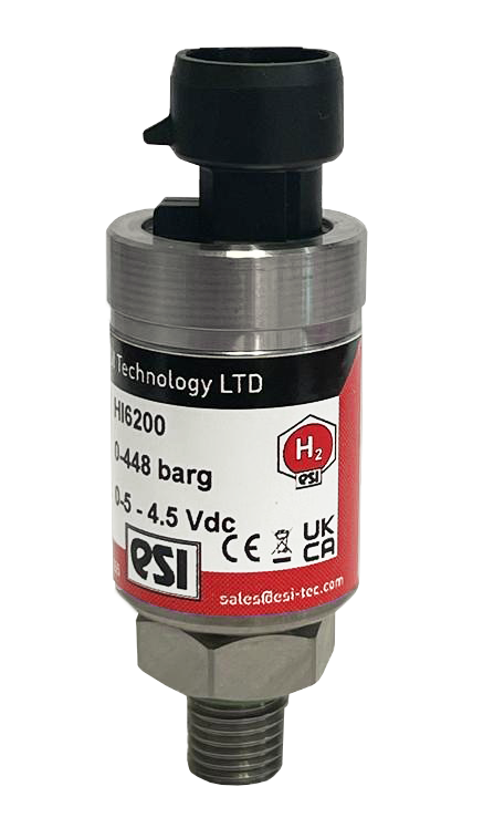
As the world transitions to clean energy, hydrogen pressure sensors have become mission-critical components in fuel cell vehicles operating at 10,150 PSI (700 bar), industrial electrolyzers producing ultra-pure H₂, and refueling infrastructure where sensor failure could trigger catastrophic explosions. Unlike conventional pressure measurement applications, hydrogen service presents unique challenges: hydrogen embrittlement cracking metal diaphragms, permeation through sensor materials causing drift and safety hazards, and explosive atmosphere regulations demanding
SUCO ESI North America offers hydrogen pressure sensor solutions, including transducers that combine titanium alloy wetted parts, tested for hydrogen compatibility, with Silicon-on-Sapphire technology for long-term stability. This comprehensive guide explores everything engineers need to know about specifying, installing, and maintaining pressure sensors in hydrogen applications—from fuel cell vehicles to production facilities, refueling stations to pipeline distribution.
Understanding Hydrogen’s Unique Challenges for Pressure Measurement
Why Hydrogen Service Requires Specialized Sensors
Hydrogen’s molecular and chemical properties create measurement challenges unknown in conventional industrial gases:
1. Hydrogen Embrittlement
The Problem: Hydrogen atoms are small enough (0.1 nanometers) to diffuse into metal crystal lattices, accumulating at grain boundaries and microscopic defects. Under mechanical stress (like diaphragm flexing), these hydrogen concentrations cause brittle crack formation and propagation—even in normally ductile materials like stainless steel.
Impact on Sensors:
- Cracks propagate rapidly under pressure cycling, causing catastrophic sudden failure
- Embrittlement accelerates at elevated temperatures and high pressures (>350 bar)
- No visual warning signs before failure—sensors appear normal until sudden rupture
Solution: SUCO ESI hydrogen sensors such as the GS4200H use a specialist high-strength titanium alloy sensor, tested for hydrogen compatibility, combined with Silicon-on-Sapphire sensing technology.
2. Hydrogen Permeation
The Problem: Hydrogen molecules diffuse through materials that completely block larger gas molecules. This permeation occurs through:
- Diaphragm penetration: H₂ migrating through thin metal diaphragms into sensor cavities
- Seal degradation: Hydrogen attacking elastomer O-rings and gaskets
- Housing penetration: Slow H₂ diffusion through threaded connections and welds
Impact on Sensors:
- Accumulated hydrogen inside sensor causes pressure on reference side, creating zero drift
- Span drift from hydrogen-induced changes in sensing element properties
- Internal pressure buildup potentially causing housing rupture
- Hydrogen release into electrical enclosures creating explosion hazard
Solution: Choose diaphragm and seal materials with documented hydrogen compatibility, and use vented enclosures so that any permeated hydrogen can escape safely.
3. Explosive Atmosphere Regulations
The Problem: Hydrogen forms explosive mixtures with air at concentrations of 4-75% (compared to 5-15% for gasoline vapors), with incredibly low ignition energy (0.02 mJ vs. 0.24 mJ for gasoline). Any electrical spark can cause ignition.
Regulatory Requirements:
| Application | Zone Classification | Required Sensor Certification | Examples |
|---|---|---|---|
| Hydrogen Storage Vessels | Zone 0 (continuous presence) | ATEX/IECEx ia/ib or Ex d | Fuel cell vehicle tanks, bulk storage |
| Dispenser Nozzles | Zone 1 (likely during operation) | ATEX/IECEx Ex d or ia | Refueling station dispensers |
| Production Facilities | Zone 2 (abnormal conditions) | ATEX/IECEx Ex nA or ia | Electrolyzer buildings, compressor rooms |
| Pipeline Distribution | Zone 2 | ATEX/IECEx Ex nA | Transmission pipelines, valve stations |
Certification Requirements: ATEX certification for Europe, IECEx for international markets, and UL/CSA for North America. Optional ATEX/IECEx versions of the GS4200H cover Zone 0, Zone 20 and Group I M1, and a DNV-approved marine variant is available.
Hydrogen-Compatible Sensor Design Features
Material Selection for H₂ Service
Recommended Approach: Choose diaphragm and wetted materials with documented hydrogen compatibility testing. SUCO ESI’s GS4200H series combines titanium alloy wetted parts, tested according to ISO 11114-2:2017, with SoS sensing.
Seal Materials for Hydrogen Compatibility
- FFKM (Kalrez, Chemraz): Excellent hydrogen resistance, low permeation, -20°C to +325°C (expensive)
- Viton (FKM): Good resistance, acceptable permeation, -20°C to +200°C (cost-effective)
- EPDM: Moderate resistance for low-pressure applications, -50°C to +150°C
- PTFE: Excellent chemical resistance, low permeation, -200°C to +260°C (limited sealing capability, requires metal backup)
Avoid: NBR (Buna-N) and natural rubber—both swell and degrade rapidly in hydrogen service.
Gold Plating: The Hydrogen Diffusion Barrier
Gold plating provides a critical protective layer preventing hydrogen permeation:
How Gold Plating Works
- Dense Crystal Structure: Gold’s FCC crystal lattice has minimal interstitial spaces preventing hydrogen diffusion
- Noble Metal Properties: Gold doesn’t form hydrides or react with hydrogen chemically
- Adhesion Layer: Nickel strike layer ensures gold adhesion to stainless steel substrate
Fuel Cell Vehicle Applications
Type IV Composite Tank Pressure Monitoring (700 bar / 10,150 PSI)
Modern fuel cell vehicles store hydrogen at 700 bar in carbon fiber composite tanks requiring precise pressure measurement:
Technical Requirements
- Pressure Range: 0-10,000 PSI or 0-15,000 PSI (allowing headroom above 700 bar working pressure)
- Accuracy: ±0.5% to ±1.0% for fuel gauge accuracy and safety monitoring
- Temperature Range: -40°C to +85°C (ambient extremes plus refueling thermal transients)
- Response Time: <100 ms for fast refueling monitoring (0 to 700 bar in 3-5 minutes)
- Service Life: 15-20 years / 500,000 km automotive durability
- Vibration/Shock: 10g continuous vibration, 50g shock per automotive standards
- EMC: Immunity to automotive electrical noise (ISO 11452)
Safety-Critical Functions
Hydrogen pressure sensors in fuel cell vehicles enable critical safety systems:
- Overpressure Protection: Prevents tank pressure exceeding 875 bar (125% of working pressure) through relief valve actuation
- Refueling Control: Monitors fill rate, prevents overfilling, controls cooling during fast fill
- Leak Detection: Pressure decay testing identifies tank or fitting leaks
- Crash Safety: Triggers tank isolation valves in collision events
- Range Calculation: Accurate fuel gauge requires ±0.5% pressure accuracy
Refueling Temperature Compensation
Rapid compression during refueling heats hydrogen significantly (up to +85°C from -40°C ambient):
- Sensors must maintain accuracy across 125°C temperature swing in 3-5 minutes
- Temperature compensation algorithms account for gas temperature effects on density
- Silicon-on-Sapphire sensors such as the GS4200H have typical thermal zero and span coefficients of ±0.015 %FS/°C
- Fast thermal response times (<5 seconds) ensure accurate pressure reading during temperature transients
Hydrogen Fuel Cell Stack Pressure Control
Fuel cell stacks operate at 1-3 bar (15-45 PSI) requiring precise anode and cathode pressure control:
Application Requirements
- Low Pressure Range: 0-100 PSI typical for stack monitoring
- High Accuracy: ±0.25% to ±0.5% for optimal stack performance
- Fast Response: <10 ms response time tracking rapid load changes
- Differential Capability: Measure pressure difference across stack (anode-cathode) preventing membrane damage
- Humidity Tolerance: Operation in 100% RH environment with water condensation
Hydrogen Production and Industrial Applications
Electrolyzer Pressure Monitoring
Electrolyzers produce hydrogen from water using electricity, operating at 10-80 bar depending on technology:
PEM (Proton Exchange Membrane) Electrolyzers
| Parameter | Requirement | Sensor Specification |
|---|---|---|
| Operating Pressure | 30-80 bar (435-1160 PSI) | 0-2000 PSI range typical |
| Hydrogen Purity | 99.999% (ultra-pure) | Contamination-free materials (sapphire, gold, titanium) |
| Temperature | 50-80°C operating | -20°C to +125°C sensor rating |
| Environment | Acidic (pH 1-3 PEM) | Acid-resistant materials, PTFE/FFKM seals |
| Accuracy | ±0.5-1.0% for process control | SoS technology for long-term stability |
Alkaline Electrolyzers
- Operating Pressure: 10-30 bar (145-435 PSI), some high-pressure designs to 80 bar
- Environment: Alkaline (30% KOH solution, pH 14)
- Material Requirements: Resistant to strong bases, typically 316L stainless or nickel alloys
- Seal Materials: EPDM or FFKM for alkaline compatibility
- Temperature: 60-90°C operating, sensors rated -20°C to +125°C
Hydrogen Compression and Storage
Industrial hydrogen facilities compress gas for storage and transportation, requiring sensors for multiple pressure stages:
Multi-Stage Compressor Monitoring
- Inlet (Suction): 0-100 PSI monitoring compressor inlet from electrolyzer or pipeline
- Interstage Pressures: 100-1000 PSI per stage (typical 3-5 stage compression to 350-700 bar)
- Discharge Pressure: 0-15,000 PSI final compression pressure
- Cooling Systems: 0-500 PSI intercooler and aftercooler monitoring
Bulk Storage Monitoring
Large-scale hydrogen storage systems (tube trailers, stationary tanks, underground caverns) require reliable long-term monitoring:
- Tube Trailers: 200-500 bar (2900-7250 PSI) transport pressure requiring sensors at each tube bundle
- Stationary Vessels: 350-700 bar storage with remote monitoring, annual calibration impractical
- Underground Storage: Salt caverns or depleted gas fields requiring corrosion-resistant sensors for 20+ year service
- Buffer Storage: Refueling station on-site storage (350-900 bar) with rapid pressure cycling from dispensing events
Hydrogen Refueling Station Applications
Station Architecture and Sensor Locations
A typical 700 bar hydrogen refueling station requires 15-25 hydrogen pressure sensors at critical points:
Delivery and Storage (6-8 sensors)
- Tube trailer connection points (2-4 sensors)
- Low-pressure buffer storage (350 bar) inlet/outlet
- Medium-pressure buffer storage (500 bar) inlet/outlet
- High-pressure buffer storage (900 bar) inlet/outlet
Compression System (4-6 sensors)
- Compressor inlet (low-pressure side)
- Interstage pressures (2-3 sensors depending on stages)
- Compressor discharge (high-pressure side)
- Cooling system monitoring
Dispensing System (3-5 sensors per dispenser)
- Pre-cooling heat exchanger monitoring
- High-pressure accumulator
- Dispenser nozzle pressure (700 bar nominal)
- Breakaway coupling safety monitoring
- Vehicle receptacle verification
Safety Systems (2-4 sensors)
- Emergency shutdown system
- Leak detection and area monitoring
- Fire suppression system actuation
Refueling Protocol Requirements (SAE J2601)
The SAE J2601 standard governs hydrogen vehicle refueling, placing demanding requirements on hydrogen pressure sensors:
Critical Parameters
- Accuracy: ±2% of reading for vehicle tank pressure measurement
- Response Time: <100 ms for safety shutdown detection
- Temperature Measurement: Integrated T-measurement for density compensation (±2°C accuracy)
- Pressure Ramp Rate Control: 20-100 PSI/second monitoring requiring fast sensor response
- End-of-Fill Detection: ±1% accuracy at target pressure (700 bar nominal, 875 bar maximum)
Communication Protocols
Modern refueling stations require digital sensor communication:
- Modbus RTU/TCP: Most common for station-level control systems
- PROFIBUS/PROFINET: European stations using Siemens PLCs
- EtherNet/IP: North American stations with Allen-Bradley/Rockwell control
- 4-20mA with HART: Legacy systems and remote monitoring applications
Installation and Maintenance Best Practices
Installation Guidelines for Hydrogen Service
Process Connection Installation
- Thread Sealants: Use ONLY hydrogen-compatible thread sealants or PTFE tape. Standard pipe dope may contain oils that contaminate ultra-pure hydrogen
- Torque Specifications: Follow manufacturer torque specs precisely—over-torquing induces mechanical stress causing zero shift
- Orientation: Install sensors with process connection below electronics for gas service, preventing moisture/condensate entering electrical housing
- Vibration Isolation: Mount sensors away from compressors/pumps using isolation brackets or flexible hose sections
Electrical Installation in Hazardous Areas
ATEX/IECEx installations demand rigorous compliance:
- Cable Glands: Use certified Ex glands maintaining ingress protection (IP65+ minimum)
- Conduit Sealing: Seal conduit entries per local codes preventing gas migration into non-hazardous areas
- Grounding: Establish single-point ground at control panel, shield grounded at one end only
- Intrinsic Safety Barriers: When using ia/ib sensors, ensure barriers properly rated and installed per certification
- Documentation: Maintain installation documentation proving compliance with certification requirements
Calibration and Verification for Hydrogen Sensors
Initial Commissioning Calibration
- Zero Verification: Verify zero reading at atmospheric pressure (gauge sensors) or vacuum (absolute sensors)
- Span Verification: Apply known reference pressure at 50% and 100% of range using calibrated test equipment
- Temperature Compensation Check: Verify accuracy at temperature extremes (-40°C, +25°C, +85°C typical)
- Documentation: Record as-found and as-left values with NIST-traceable reference standards
Best Practice: For critical applications, implement online verification using redundant sensors cross-checking each other, reducing calibration frequency while maintaining safety integrity.
Troubleshooting Hydrogen Sensor Issues
Symptom: Progressive Zero Drift
Likely Causes:
- Hydrogen permeation through diaphragm accumulating behind sensing element
- Seal degradation allowing hydrogen entry into electronics cavity
- Temperature cycling causing mechanical stress in bonding agents (standard sensors)
Solutions:
- Replace sensor with gold-plated diaphragm design preventing permeation
- Upgrade to SoS technology eliminating bonding agent degradation
- Verify installation orientation preventing condensate accumulation
- Check seal materials—upgrade to FFKM if using Viton/EPDM
Symptom: Premature Sensor Failure (Diaphragm Rupture)
Likely Causes:
- Hydrogen embrittlement causing crack propagation in stainless steel diaphragm
- Pressure cycling fatigue (common in refueling station dispensers)
- Overpressure events exceeding burst rating
Solutions:
- Specify titanium or Inconel diaphragm materials for embrittlement resistance
- Add inline pressure snubbers damping rapid pressure changes
- Install overpressure protection (relief valves) upstream of sensors
- Upgrade to sensors with higher burst pressure ratings (5x vs. 3x full scale)
Specification Checklist for Hydrogen Pressure Sensors
Required Specifications
When specifying hydrogen pressure sensors, ensure documentation includes:
Performance Requirements
- Pressure Range: Sized to 60-70% of full scale under normal operation
- Accuracy: ±0.25% to ±1.0% depending on application criticality
- Reference Type: Gauge (most H₂ applications) or absolute (altitude-independent)
- Operating Temperature: -40°C to +85°C minimum for outdoor installations
- Response Time: <100 ms for safety applications, <10 ms for control loops
- Long-term Stability: <0.2% per year for reduced calibration frequency
Material Requirements
- Diaphragm Material: Gold-plated 316L, titanium, or Inconel 718
- Wetted Materials: All process-contact materials per ISO 11114-2:2017 testing
- Seal Materials: FFKM or Viton with documented hydrogen compatibility
- Housing Material: 316 stainless or aluminum (ATEX-compliant)
- Sensing Technology: Silicon-on-Sapphire preferred for critical applications
Certification Requirements
- ATEX/IECEx: Zone 0/1 certification (II 1/2 G Ex ia/ib IIC T6 typical)
- ISO 11114-2:2017: Materials compatibility testing for hydrogen service
- UL/CSA: Class I, Division 1 or Zone 0 for North American installations
- SIL 2/3: Functional safety certification per IEC 61508 for safety systems
- EMC Compliance: EN 61326 for industrial electromagnetic compatibility
SUCO ESI Hydrogen Pressure Sensor Solutions
SUCO ESI North America offers a range of hydrogen pressure sensors, including the GS4200H, HI6200H, HI2000H and HP1000H hydrogen-compatible pressure transducers and a line of hydrogen pressure switches.
GS4200H Hydrogen Sensor Series
Our GS4200H series combines Silicon-on-Sapphire technology with hydrogen-specific design features:
- Specialist high-strength titanium alloy sensor with titanium alloy wetted parts
- SoS sensing element providing excellent long-term stability
- Optional ATEX/IECEx approval (4-20 mA version: Ex II 1 G Ex ia IIC T4 Ga, zone 0)
- ISO 11114-2 tested materials documented hydrogen compatibility
- Pressure ranges: vacuum to 1,500 bar (20,000 psi)
- Operating temperatures: ambient -40 °C to +85 °C, media -50 °C to +125 °C
- Multiple outputs: 4-20 mA, 0-5 V, 0-10 V and 10 mV/V
Why Specify SUCO ESI for Hydrogen Applications?
- Certifications: optional ATEX/IECEx approval, DNV marine approval, and ISO 11114-2:2017 hydrogen compatibility testing
- SoS Technology: Silicon-on-Sapphire sensing with exceptional long-term stability and reduced drift compared to conventional silicon sensors
- North American Support: ESI transducers manufactured in Wrexham, UK, with sales and support from St. Louis, MO and Deerfield Beach, FL
- Application Engineering: Expert guidance for complex hydrogen measurement challenges
Contact SUCO ESI for Hydrogen Sensor Solutions
Phone: 1-800-473-7313
Website: www.sucoesi.com
Contact: Request Technical Support
LinkedIn: Connect with SUCO ESI
Related Resources:
- Complete Guide to Electrical Pressure Sensors
- Browse Hydrogen Sensor Product Line
- Download H₂ Sensor Datasheets & Certifications
The hydrogen economy depends on safe, reliable pressure measurement. Hydrogen pressure sensors from SUCO ESI combine advanced materials, Silicon-on-Sapphire technology, and decades of application expertise to ensure your fuel cell vehicles, production facilities, and refueling infrastructure operate safely and efficiently for years to come.