How Pressure Switches Work: Operating Principles Explained
Pressure switches are essential control and safety components used throughout industrial systems, yet their operating principles are often misunderstood during specification and selection. These electromechanical devices monitor system pressure and convert predefined pressure levels into electrical switching signals. By doing so, pressure switches enable automated control, protect equipment, and prevent hazardous overpressure or vacuum conditions.
A clear understanding of how pressure switches work is critical for correct application, reliable operation, and long-term performance—especially in industries where system failure can lead to costly downtime, equipment damage, or safety risks.
Fundamental Pressure Switch Working Principle
The basic pressure switch working principle is the conversion of mechanical force—generated by pressurized media—into an electrical on/off signal. When system pressure reaches a preset value (the setpoint), the pressure switch activates or deactivates an electrical circuit.
Unlike pressure sensors or transducers that output continuous analog signals, pressure switches operate in a binary mode. This makes them ideal for alarm functions, pump control, compressor protection, and safety interlocks.
 Basic Operation Sequence
The operating cycle of a mechanical pressure switch typically follows these steps:
- Process pressure acts on the sensing element
- The sensing element deflects proportionally to the applied pressure
- Mechanical motion transfers to a switching mechanism
- At the setpoint, electrical contacts snap open or closed
- When pressure drops below the reset value (differential), the contacts return to their original state
The snap-action design ensures fast, decisive contact movement rather than gradual switching. This minimizes contact arcing, prevents welding, and improves electrical reliability.
The pressure differential; usually 5–15% of the setpoint; prevents rapid on/off cycling, which could otherwise damage electrical loads or create unstable control behavior.
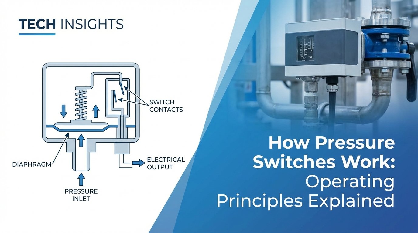
Core Components of Pressure Switch Design
A pressure switch consists of several integrated components that work together to ensure accurate and reliable operation. Reviewing a typical pressure switch diagram helps illustrate how mechanical and electrical elements interact within the device.
Pressure Sensing Elements
The sensing element is the wetted component that directly contacts the process media and converts pressure into mechanical displacement. Common sensing technologies include:
-
Diaphragms – Ideal for low-pressure applications and corrosive media. When manufactured from materials such as Hastelloy, Monel, or PTFE-coated stainless steel, diaphragms provide excellent chemical resistance and sensitivity.
-
Bourdon Tubes – These curved metal tubes straighten as pressure increases, making them suitable for high-pressure applications above 10,000 PSI. They are widely used in industrial and hydraulic systems.
-
Pistons – Designed for rugged environments, piston-type pressure switches offer high durability and resistance to pressure spikes and contaminated fluids, though they typically require higher actuation forces.
Advanced Sensing Technologies
Silicon-on-Sapphire (SoS) technology combines a sapphire diaphragm with a silicon strain gauge layer. This advanced design delivers exceptional chemical resistance, thermal stability, and measurement accuracy. SoS pressure switches perform reliably in extreme temperatures ranging from −40°C to +200°C and are commonly used in aerospace, oil and gas, and chemical processing applications.
Switching Mechanism
The switching mechanism converts sensing element movement into electrical contact action. Most industrial pressure switches use snap-action microswitches, which rely on a spring-loaded toggle system to produce fast, repeatable contact transitions regardless of actuator speed.
This design offers several advantages:
- Reduced contact bounce
- Lower electrical noise
- Extended service life (often millions of cycles)
For hazardous or sensitive environments, magnetically coupled pressure switches are used. In these designs, a magnet attached to the sensing element actuates an external magnet linked to the electrical contacts. This eliminates mechanical shaft penetration, providing complete isolation between process media and electrical components—an essential feature for ATEX and IECEx certified applications.
Housing and Connection Options
The pressure switch housing protects internal components from environmental exposure while providing secure electrical connections. Common housing materials include:
- Die-cast aluminum for general industrial use
- 316L stainless steel for corrosive or hygienic environments
- High-performance polymers for lightweight or chemically aggressive applications
Ingress protection ratings such as IP65 and IP67 indicate resistance to dust and water ingress, which is critical for outdoor, washdown, or offshore installations.
Electrical Connections
Pressure switches are available with multiple electrical termination options, including:
- Screw terminals
- Plug connectors (M12, DIN 43650)
- Pre-wired flying leads
Correct cable gland selection is essential to maintain the housing’s ingress protection rating, particularly in wet, dusty, or subsea environments

Types of Pressure Switches and Operating Characteristics
Multiple types of pressure switches exist, each optimized for specific operational parameters and application requirements.
Mechanical Pressure Switches
Purely mechanical designs offer inherent reliability through simple, proven technology. No external power requirement makes these switches ideal for emergency shutdown systems and fail-safe applications. Adjustment mechanisms typically involve spring preload changes via screw adjusters or interchangeable springs for different pressure ranges.
The main limitation involves fixed switching characteristics—once installed, setpoint changes require physical access and manual adjustment. However, this immutability provides security against unauthorized tampering in safety-critical applications.
Electronic Pressure Switches
Electronic pressure switches integrate a pressure sensor element with signal conditioning electronics and programmable switching outputs. These devices combine the continuous monitoring capabilities of pressure transmitters with the discrete switching function of mechanical switches.
Advantages include precise digital setpoint programming, multiple switching points from a single device, and diagnostic capabilities like sensor health monitoring. Many electronic pressure switches communicate via IO-Link or fieldbus protocols, enabling remote configuration and integration with Industry 4.0 systems.
The tradeoff involves increased complexity and power requirements. Electronic switches need stable power supplies and offer reduced reliability in extreme electromagnetic interference environments without proper shielding.
Differential Pressure Switches
Differential pressure switches monitor the pressure difference between two points rather than absolute pressure. Filter monitoring represents the classic application—as a filter clogs, differential pressure increases until the switch triggers a maintenance alarm or initiates automatic backwashing.
These switches incorporate two sensing ports acting on opposite sides of a diaphragm or differential piston. The net force determines switching action, making these devices insensitive to simultaneous pressure changes affecting both ports equally.
Vacuum and Compound Switches
Vacuum switches activate at pressures below atmospheric, essential for monitoring vacuum pumps, packaging equipment, and material handling systems. Compound switches handle both positive and negative gauge pressure, suitable for systems experiencing pressure reversals.
Special sealing considerations apply since external atmospheric pressure can force contamination into the housing during vacuum conditions. Diaphragm-based sensing elements typically perform better than Bourdon tubes in vacuum service due to their larger active area and higher sensitivity.
Critical Pressure Switch Selection Parameters
Correct pressure switch selection depends on more than matching the pressure range. Application conditions, media properties, and electrical loads all influence performance and service life.
Pressure Range and Switching Accuracy
Choose a pressure switch with a range that covers normal operating pressure and expected pressure spikes. For best accuracy and durability, operate the switch within the middle 60% of its rated range.
Switching accuracy defines how closely the switch activates at the setpoint. Typical accuracy ranges from ±2% to ±5% of full scale.
Repeatability measures how consistently the switch activates over multiple cycles. High-quality pressure switches achieve ±0.5% repeatability, which helps maintain stable and repeatable process control.
Media Compatibility and Temperature Limits
All wetted materials must be compatible with the process media, including gases, liquids, and condensates. 316L stainless steel suits most industrial fluids, while aggressive chemicals, seawater, and hydrogen require specialized alloys or coatings.
Hydrogen applications present additional risk due to hydrogen embrittlement, which can weaken metal structures over time.
Temperature affects both sensing elements and seals. NBR seals typically operate from −20°C to +100°C, while FKM seals extend performance up to +150°C. Silicon-on-Sapphire sensors maintain accuracy across extreme temperatures without the mechanical drift seen in bimetallic designs.
Electrical Ratings and Switching Frequency
Electrical contact ratings must exceed the actual load with a safety margin. Inductive loads, such as solenoids and relay coils, require higher ratings due to arcing during switching. A common rule is to specify contacts rated for at least 150% of the expected load current.
Switching frequency also limits service life. Most mechanical pressure switches support 10–30 cycles per minute, while electronic pressure switches handle much higher switching rates without contact wear.
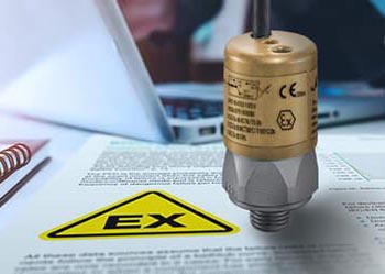 Hazardous Area Compliance and Safety
Applications in explosive atmospheres require pressure switches certified to ATEX (Europe), IECEx (International), or NEC 505/500 (North America) standards. These certifications verify that the device cannot become an ignition source even during fault conditions.
Intrinsically safe (Ex ia) designs limit electrical energy to levels incapable of igniting explosive atmospheres. This approach requires compatible intrinsically safe barriers or isolated power supplies. Flameproof/explosion-proof (Ex d) enclosures contain internal explosions without propagating ignition to external atmospheres.
Proper installation following manufacturer guidelines ensures certification validity. This includes using only approved cable glands, maintaining torque specifications, and respecting temperature class limitations. Documentation requirements demand maintaining certification paperwork and installing identification labels.
Application-Specific Considerations
Oil and Gas Operations
Upstream, midstream, and downstream facilities rely on pressure switches for wellhead monitoring, pipeline protection, and refinery process control. SIL-rated switches meeting IEC 61508 standards integrate into safety instrumented systems (SIS) providing automated shutdown during dangerous pressure conditions.
Vibration resistance proves essential on offshore platforms and near reciprocating compressors. Switches with welded construction and solid-state sensors withstand continuous vibration that would fatigue mechanical joints and brazed connections.
Aerospace and Defense
Aircraft hydraulic systems, environmental control, and fuel management demand lightweight, highly reliable pressure switches operating across extreme temperature ranges and altitude changes. Qualification testing to AS9100 standards and specific aircraft manufacturer requirements ensures performance during the entire service life without field failures.
Weight optimization drives miniaturization efforts, with titanium housings and integrated connectors reducing mass while maintaining structural integrity during high G-force maneuvers.
Hydrogen Energy Systems
Emerging hydrogen production, storage, and fuel cell applications present unique challenges. Hydrogen’s small molecular size causes permeation through materials, while high-pressure storage (700+ bar) demands robust construction. Specialized austenitic stainless steels and nickel alloys resist hydrogen embrittlement.
Pressure switches monitor electrolyzer operation, compression stages, and vehicle refueling safety systems. Rapid response times enable protective shutdowns before catastrophic pressure vessel failure.
Installation and Maintenance Best Practices
Correct installation is essential for pressure switch accuracy, reliability, and service life. Improper mounting or exposure to unstable pressure conditions is one of the most common causes of premature pressure switch failure.
Best practices for pressure switch installation include:
- Mount the pressure switch so the pressure port orientation prevents sediment buildup and air entrapment
- Use isolation valves to allow switch removal or replacement without depressurizing the system
- Avoid mounting locations exposed to excessive vibration or mechanical stress
- Verify electrical load ratings match the switch contact specifications
In systems with rapid pressure fluctuations—such as those using reciprocating pumps or fast-acting valves—pressure pulsation protection is critical. Pulsation dampeners, snubbers, or chemical seals reduce shock loading while maintaining accurate pressure transmission to the sensing element.
Routine maintenance ensures consistent setpoint accuracy and reliable switching performance. Periodic functional testing verifies correct actuation and reset behavior. In safety-related applications, proof testing at defined intervals, based on reliability calculations or safety standards, confirms the pressure switch will perform its protective function when required.
Troubleshooting Common Issues
Most pressure switch failures are not caused by internal defects but by application or installation errors. Identifying the root cause quickly helps prevent repeated failures and system downtime.
Common pressure switch problems and likely causes include:
- No switching or delayed response: Pressure spikes exceeding rated limits or blocked pressure ports
- Erratic or unstable switching: Mechanical hysteresis from sensing element fatigue or contamination
- Shifted setpoint or calibration drift: Chemical deposits altering diaphragm elasticity or spring characteristics
- Electrical contact failure: Loads exceeding contact current or voltage ratings
Contamination is a frequent contributor to erratic performance. Process media deposits on diaphragms or pistons change the mechanical response of the sensing element, resulting in inaccurate switching. Regular inspection and cleaning during scheduled maintenance cycles significantly reduce these issues and extend service life.
The Shift Toward Smart Pressure Monitoring
Industrial pressure monitoring is evolving beyond simple on/off control. Modern intelligent pressure switches combine traditional switching functionality with continuous pressure measurement and digital communication capabilities.
These hybrid devices provide real-time pressure data to control systems while maintaining discrete switching outputs for safety functions. Integrated diagnostics—such as switching cycle counters, temperature compensation status, and sensor drift alerts—support predictive and condition-based maintenance strategies.
By identifying performance degradation early, smart pressure switches help reduce unplanned downtime, optimize maintenance resources, and improve overall system reliability.
Application Engineering and Technical Support
Selecting the correct pressure switch requires careful evaluation of pressure range, media compatibility, environmental conditions, electrical loads, and safety requirements. Application-specific engineering support ensures these parameters are properly balanced for long-term performance.
Need help selecting the right pressure switch? Contact our technical team for application support, documentation, and configuration guidance.
📧 Email: sales@sucoesi.com
📞 Phone: 1-561-989-8499